 Beijing TransFar Electronics Group Co., Ltd
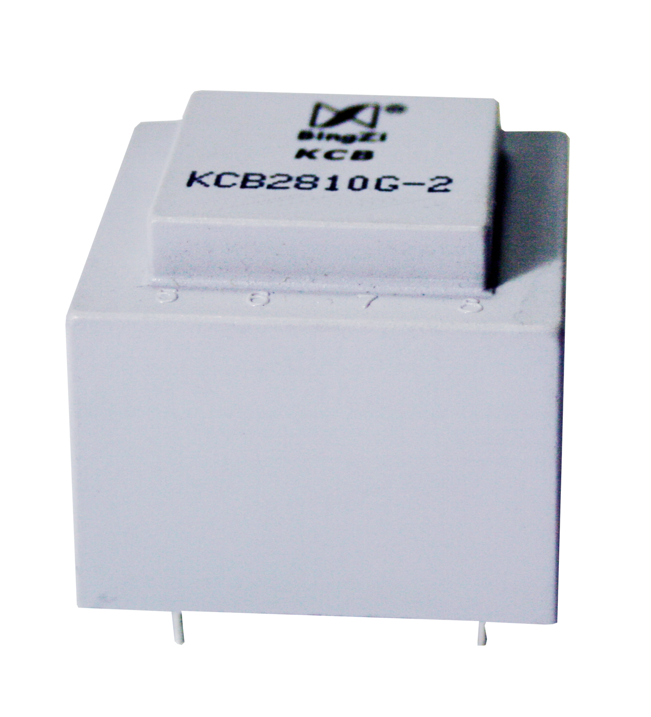
KCB -G Series High Voltage Thyristor Trigger Transformer
LI094V2/2016
1. Features:
①Fully enclosed printed circuit board directly welded and installed ;
②Strong mechanical and environmental isolation ability, compact structure, strong, anti-vibration, moisture-proof, flame retardant ;
③The electric strength between each winding is high ;
④The required transformation ratio can be formed by itself to meet the triggering requirements ;
⑤Compatible with thyristors of all capacities ;
⑥It can be used as an ordinary pulse transformer.
2. Application:
The trigger transformer is used in conjunction with the thyristor, and is usually connected between the control trigger unit and the thyristor control pole in the thyristor device. On the one hand, it transmits the trigger pulse, and on the other hand, it reliably isolates the strong and weak currents. effect. This series of trigger transformers can be widely used in:
①Pressure regulating and speed regulating equipment ⑤Rectifier
②Welding machine⑥ Inverter frequency conversion equipment
③Elevator⑦automatic control device
④Intermediate frequency power supply⑧Other thyristor devices
A typical application circuit is as follows:

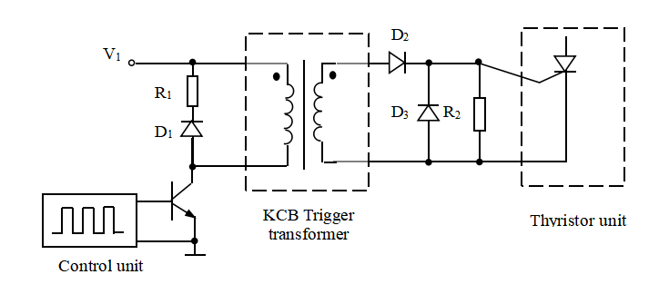

Description: 1. R1 and D1 mainly play the role of freewheeling. D1 can generally choose 1N4007, R1 can choose 1kΩ~2kΩ;
2. D2 , D3 , and R 2 mainly play the role of shaping. D2 and D3 can choose 1N4007, and R2 can choose tens to hundreds of ohms.
3. Comparison table of typical characteristics of each Model:
SN | Model | u | Test frequency | ∫udt (μV s ) | Withstand voltage (kV) | Dimensions Tolerance ±0.5(mm) | Weight (g) | Page |
1 | KCB 1607G-1 | 1:1 | 1 00Hz | 1200 | 5 | 20 x 18 x 18.5 | 15 | 163 |
2 | KCB 1607G-2 | 2:1 | 1 00Hz | 1800 | 5 | 20 x 18 x 18.5 | 15 | 163 |
3 | KCB 1607G-3 | 3:1 | 1 00Hz | 2880 | 5 | 20 x 18 x 18.5 | 15 | 163 |
4 | KCB 1908G-1 | 1 :1 | 1 00Hz | 1600 | 6 | 21.6 × 21 × 18.5 | 20 | 163 |
5 | KCB 1908G-2 | 2 :1 | 1 00Hz | 2250 | 6 | 21.6 × 21 × 18.5 | 20 | 163 |
6 | KCB 1908G-3 | 3 :1 | 1 00Hz | 3600 | 6 | 21.6 × 21 × 18.5 | 20 | 163 |
7 | KCB 2410G-1 | 1:1 | 1 00Hz | 3200 | 8 | 27×23.6×22 | 100 | 163 |
8 | KCB 2410G-2 | 2:1 | 1 00Hz | 6000 | 8 | 27×23.6×22 | 100 | 163 |
9 | KCB 2410G-3 | 3:1 | 1 00Hz | 9600 | 8 | 27×23.6×22 | 100 | 163 |
10 | KCB 2810G-1 | 1:1 | 3kHz | 1000 | 15 | 31×31×25.6 | 70 | 164 |
11 | KCB 2810G-2 | 2:1 | 7kHz | 1200 | 15 | 31×31×25.6 | 70 | 164 |
12 | KCB 2810G-3 | 3:1 | 7kHz | 1200 | 15 | 31×31×25.6 | 70 | 164 |
13 | KCB 4916G-1 | 1 :1 | 1k Hz | 200 0 | 20 | 73.7 × 53.8 × 31 | 300 | 164 |
14 | KCB 4916G-2 | 2 :1 | 3kHz | 3000 | 20 | 73.7 × 53.8 × 31 | 300 | 164 |
15 | KCB 4916G-3 | 3 :1 | 3kHz | 3000 | 20 | 73.7 × 53.8 × 31 | 300 | 164 |
4. User Guide:
①First, determine the required dielectric strength V P according to the working voltage V 0 (effective value) of the system . It can be selected according to the recommendation in Table 1:
Table 1:
Operating Voltage V 0 | 220V | 380V | 500V | 800V | 1100V | 1400V | 2000V | 3000V |
Dielectric strength Vp | 1.9kV | 3.1kV | 4.5kV | 6kV | 8.3kV | 10kV | 15kV | 20kV |
②According to the different needs of customers, we have recently launched a high withstand voltage trigger transformer,
Structure | withstand voltage |
KCB4916G | 20kV |
KCB2810G | 15kV |
KCB2410G | 8kV |
KCB1908G | 6kV |
KCB1607G | 5kV |
HMB6090 | 95kV |
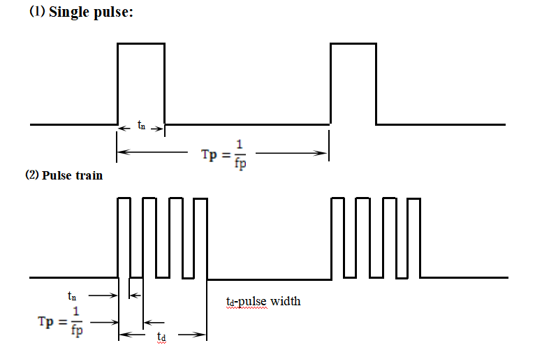
5. Trigger pulse type:
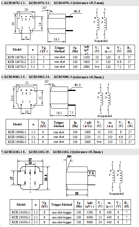
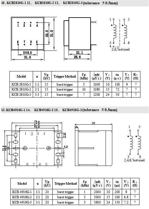
6. Outline drawing, installation size, coil diagram and detailed technical parameters:
● Description:
①The parameters given in the following tables are typical values measured at room temperature.
②The meaning of each parameter:
u-transformation ratio=Ⅰ:Ⅱ:Ⅲ:Ⅳ
Vp - the effective value of the dielectric strength test voltage applied between each winding, and the duration is 60 s .
fp - test pulse frequency (Tp is period). 100H Z represents a single pulse, and the rest represent a pulse train, and the equivalent width of the pulse train is set to td =2m s .
∫udt-Rated volt-microsecond product≈V1 ·tn (the value basically does not change within a certain frequency range)
V1 - input pulse amplitude (primary pulse voltage).
tn - the rated transmission pulse width of the transformer under the corresponding V1 and fp .
V2 - output pulse amplitude (secondary pulse voltage).
RL -SCR control electrode equivalent resistance.
