 Beijing TransFar Electronics Group Co., Ltd

1.Features:
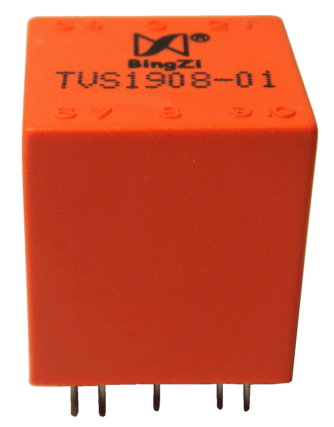
① This is an electronic current-type voltage transformer with a built-in IC amplifier inside, providing high accuracy.
② It is fully encapsulated, has strong mechanical and environmental endurance, strong dielectric strength, and is safe and reliable.
③It is light in weight, small in size, capable of being directly soldered onto a PCB, and has an elegant outline.
2.Ambient Conditions:
① Ambient temperature: -55℃~+85℃;
② Relative humidity: ≤90% at 40℃;
③ Atmospheric pressure: 860~1060mbar(about 650~800mmHg).
3.Operating Frequency Range:20Hz~10kHz
4.Insulation Thermal Class: Class B (130℃)
5.Safety Features:
① Dielectric resistance:>1000MΩ in normal condition;
② Insulation withstand voltages: 2KV 50Hz/1min;
③ Fire retardancy: In conformity with UL94-V0.
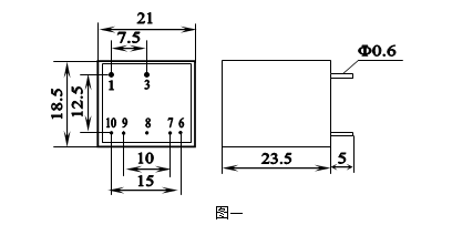
6.Outline Drawing, Installation Dimension and Function of Pins (Table below):

Pin No. | 1-3 | 6 | 7 | 8 | 9 | 10 |
Function | input | +B | adjusting | G | -B | output |
7.Models and Technical parameters as in the following table:
Model Item | TVS1908-01 | TVS1908-02 | TVS1908-03 |
Rated Input Voltage | 380Vrms | 220Vrms | 100Vrms |
Rated Output Voltage | 5Vrms | 5Vrms | 5Vrms |
Non-Linearity | ≤0.3% | ≤0.3% | ≤0.3% |
Phase Shift | ≤30’ | ≤30’ | ≤30’ |
Isolated Voltage | ≥2000V | ≥2000V | ≥2000V |
Working Power Supply | ±15V~22V | ±15V~22V | ±15V~22V |
8.Application Instructions:
① 1-3 input Pins must be connected in parallel with the loop of the measured current circuit. Pin 6 connected to +B. Pin 9 connected to –B, Pin 8 connected to ground, Pin10 is output terminal. Pin 7 is a terminal for adjusting.
② While input AC moving between 0~Rated Voltage, the output between Pin 10 and Pin 8 is 0~5V and linearly correspondent.
③ Phase shift can be compensated by connecting a capacitor between Pin 7 and Pin 10 and compensated to ≤15’ when choosing a capacitor of 0.033μF
④ Output voltage can be changed by connecting a resistor between Pin 7 and Pin 10 and it will be as bellow if the resistor connected is R and input rated voltage:

9.Attention
① Pin 8 must be connected to ground, otherwise the accuracy will be influenced.
② If you want to change the output AC signal to a DC signal, you can apply the method of absolute value rectifying. Otherwise, the linear correspondence will be damaged due to the tube voltage drop of the diode.
③ Increasing the working voltage between Pin 6 and Pin 9 can extend the scope of measuring. Contrariwise, it will reduce the scope.
④ If the output and input parameters are not suitable for you, we can customize it according to your request.