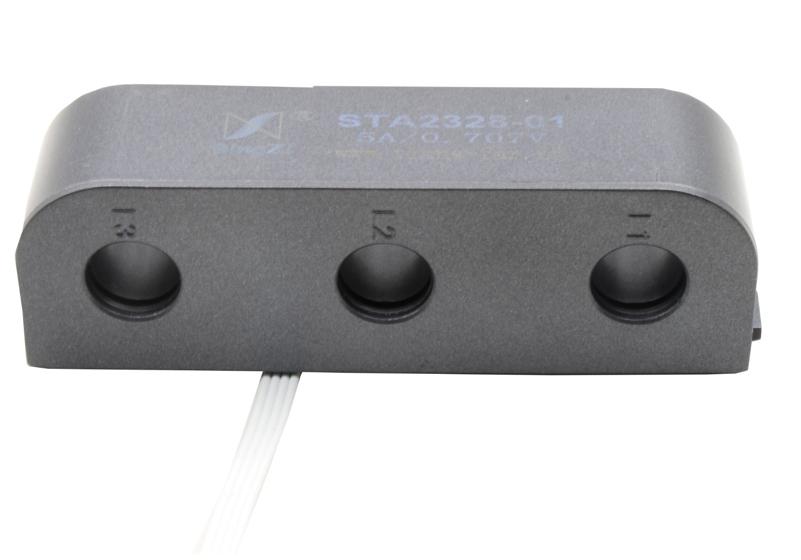
 Beijing TransFar Electronics Group Co., Ltd

1.Features:
① Vertical pass-through design for easy installation;
② Equipped with standard terminal block for convenient wiring;
③ Epoxy potting provides strong vibration resistance and aesthetic appearance.
2.Ambient Conditions:
① Ambient temperature: -55℃~+85℃;
② Relative humidity: ≤90% at 40℃;
③ Atmospheric pressure: 860~1060mbar(about 650~800mmHg).
3.Operating Frequency Range: 20Hz~1kHz
4.Insulation Thermal Class: Class B (130°C)
5.Safety Features:
① Insulation resistance: >1000MΩ in normal condition;
② Insulation withstand voltages: 3KV 50Hz/1min.
③ Fire retardancy: In conformity with UL94-V0.
④ Overload characteristics: the transformer can operate continuously at 5 times the rated current; can operate for 10 minutes at 10 times the rated current.
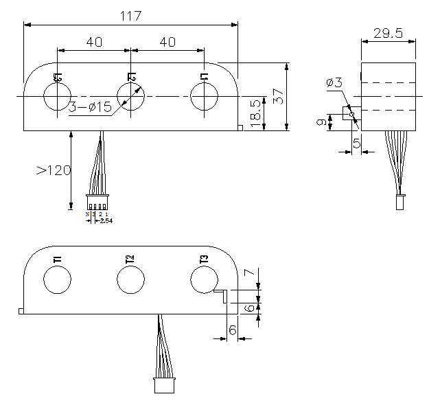
6.Outline Drawing, Installation Dimension and Coil Diagram: (tolerance±1mm)
①Outline drawing and installation dimensions are shown in Figure 1:

Fig.1
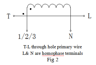
② The coil diagram is shown in Figure2:

Fig 2
7. Performance Parameters:
Performance parameters when applied as shown in Figure 3 are listed in the table below:
Model | Rated Input Current | Rated Output Current | Non-linearity |
STA2328-01 | 5A | 0.707V | ≤0.5% |
STA2328-02 | 10A | ||
STA2328-03 | 30A | ||
STA2328-04 | 50A |
8. Attention:
① Connect the primary winding of the current transformer in series in the circuit under test. Operate the secondary winding approximately in a short-circuit state.
② Do not allow the secondary circuit of the current transformer to be open-circuited. Do not install any fuses in the secondary circuit.