 Beijing TransFar Electronics Group Co., Ltd

1. Features:
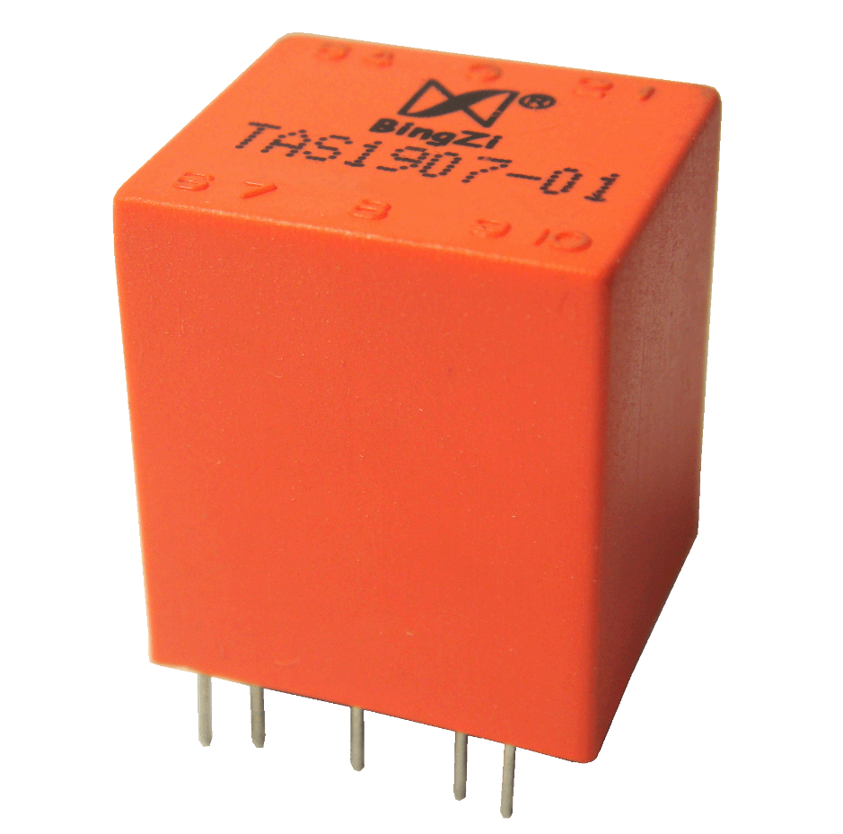
① The device takes in AC current signal as input and outputs AC voltage signal.
② It has an integrated operational amplifier, enabling high accuracy measurements.
③ It is completely sealed, ensuring strong mechanical and environmental endurance, with high dielectric strength and safe and reliable usage.
④ With an elegant and compact design, it can be directly soldered onto a PCB.
2. Ambient Conditions:
① Ambient temperature: -55℃~+85℃;
② Relative humidity: ≤90% at 40℃;
③ Atmospheric pressure: 860~1060mba(about 650~800mmHg).
3. Operating Frequency Range: 20Hz~10kHz
4. Insulation Thermal Class: Class B (130℃)
5. Safety Features:
① Dielectric resistance: >1000MΩ in normal condition;
② Insulation withstand voltages: 2KV 50Hz/1min;
③ Fire retardancy: In conformity with UL94-V0.
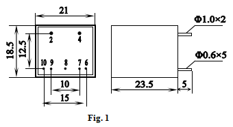
6. Outline Drawing, Installation Dimension and Function of Pins (table below):
Pin No. | 2-4 | 6 | 7 | 8 | 9 | 10 |
Function | input | +B | adjusting | G | -B | output |

7. Technical Parameters:
① Rated input current (virtual value):5A (Pin 2-4)
② Rated output voltage (virtual value): 5V (Pin 8-10)
③ Non-Linearity ≤0.3%
④ Phase Shift ≤30’
⑤ Insulating Withstand Voltage≥2000V
⑥ Working Power Supply(B)±15V~22V
8. Application Instructions:
①The input coil between Pin 2 and Pin 4 must be connected in series with the loop of the measured current circuit, Pin 6 connected to +B. Pin 9 connected to –B. Pin 8 connected to ground. Pin10 is the output terminal. Pin7 is the adjusting terminal.
② While input AC current moving between 0~5A, output of 0~5V between Pin10 and Pin 8 is obtained and is linearly correspondent.
③Phase shift can be compensated by connecting a capacitor between Pin 7 and Pin10 and compensated to ≤15’ when choosing a capacitor of 0.033μF.
④Output voltage can be changed by connecting a resistor between Pin7 and Pin10 and it will be as bellow if the resistor connected is R and input current is 5A:

9.Attention:
① Pin 8 must be connected to ground, otherwise the accuracy will be compromised.
② If you want to convert the output AC signal to a DC signal, you can use the absolute value rectification method. Otherwise, the linear relationship will be disrupted due to the voltage drop across the diode.
③ Increasing the working voltage between Pin 6 and Pin 9 can extend the measuring range, whereas decreasing it will reduce the range.
④ If the output and input parameters do not suit your needs, we can customize them according to your specifications.