 Beijing TransFar Electronics Group Co., Ltd
1.Features:
① Vertical core, flexible installation, can be fixed on the busbar or on the bottom plate;
② It can be equipped with various types of busbars, such as flat busbars, round busbars or cables;
③ The output terminal is a screw fastened crimping type standard terminal, which is convenient for wiring at the engineering site;
④ Box structure, closed plastic case, beautiful appearance.
2.Ambient Conditions:
① Ambient temperature: -30℃~+70℃;
② Relative humidity: ≤90% at 40℃;
③ Atmospheric pressure: 860~1060mbar
(about 650~800mmHg).
3.Operating Frequency Range: 20Hz~1kHz
4.Insulation Thermal Class:Class E (120°C)
5.Safety Features:
① Insulation resistance: >1000MΩ in normal condition;
② Insulation withstand voltages: 3000V 50Hz/1min;
③ Fire retardancy: In conformity with UL94-V0.
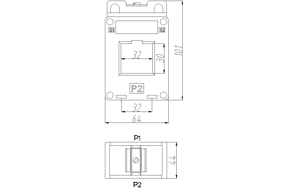
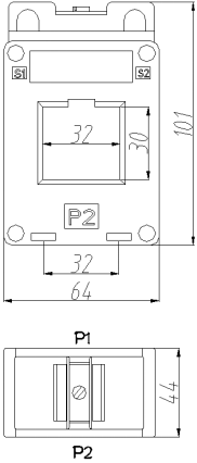
6. Outline Drawing, Installation Dimension and Coil Drawing:( tolerance ± 1mm )
① Outline drawing and installation dimensions are shown in Fig 1:
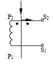
② The coil diagram is shown in Fig 2:
● Note: Each product is supplied with
two bottom plate feet, one busbar
foot, two screws and suction cups for
fixing the busbar, and the installation
instructions are as follows.
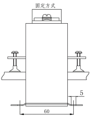
③ Installation Instructions:
● When fixing to the bottom plate: take two feet ( supplied with the product ) and insert them into the foot sockets on the bottom plate as shown in Figure 3. The center distance of the mounting holes is 60 × 32 ; the mounting hole diameter of the feet is Φ5.0; the transformer can be fixed on the bottom plate with M5 screws.
● When fixing on the busbar: take a foot with M5 holes ( supplied with the product ) and insert it into the busbar foot slot as shown in Figure 3. The center distance of the M5 holes is 5 9 , and the transformer can be fixed on the busbar with M5 screws .
7. Typical Application and Performance Parameters:
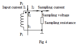
See the table below for performance parameters when applied as shown in Figure 4.
Model | Rated Input Current | Rated Output Current | Rated Sampling Resistor R L | Rated Sampling Voltage | Phase Shift | Non-linearity | Linear Range |
TAL3230-1 | 100A | 5A | 0.125Ω | 0.625V | ≤ 30' | ≤0.5% | 2 times of rated value |
TAL3230-2 | 150A | 5A | 0.188Ω | 0.938V | ≤ 30 | ≤0.5% | 2 times of rated value |
TAL3230-3 | 200A | 5A | 0.25Ω | 1.25V | ≤ 30 | ≤0.5% | 2 times of rated value |
TAL3230-4 | 250A | 5A | 0.312Ω | 1.56V | ≤ 30 | ≤0.5% | 2 times of rated value |
TAL3230-5 | 300A | 5A | 0.375Ω | 1.88V | ≤ 30 | ≤0.5% | 2 times of rated value |
TAL3230-6 | 400A | 5A | 0.5Ω | 2.5V | ≤ 30 | ≤0.5% | 2 times of rated value |
● Notes:
a. In practical applications, the sampling resistor should be less than or equal to the Rated value given in the above table, which will improve the nonlinearity and phase shift.
b. If the conversion ratio required by the user is different from the above, it can be customized according to the user's requirements.
8.Attention:
① Connect the primary of the current transformer in series with the measured current loop, and operate the secondary in near short circuit mode.
② Do not allow the secondary of the current transformer to be open circuited and do not install any fuse on the secondary.