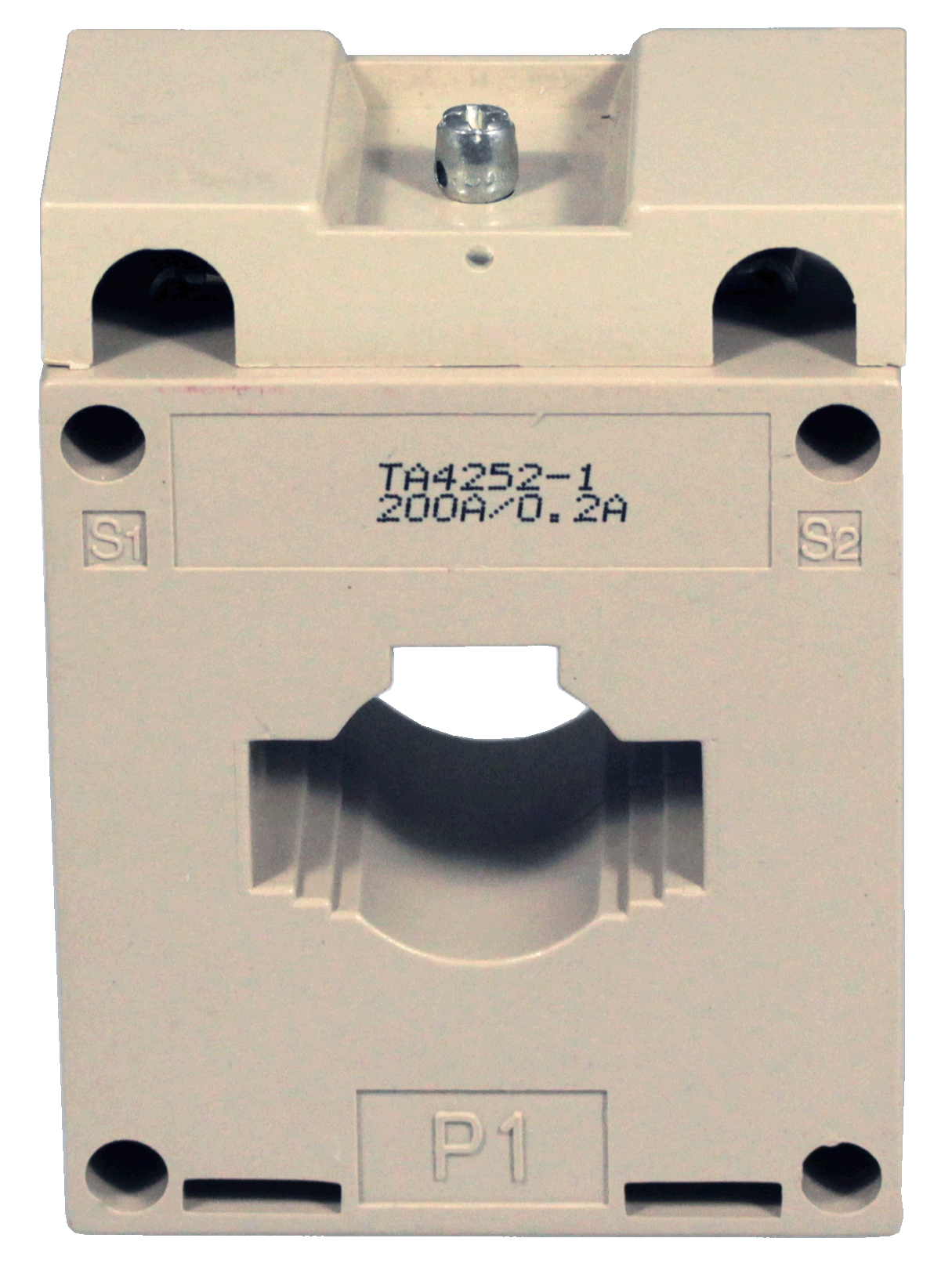
 Beijing TransFar Electronics Group Co., Ltd

1.Features:
① Flexible installation modes: can be fixed on the primary wire or bottom board.
② Compatible with various primary wires, including flat-type wires, round wires, or cables.
③ Standard output terminals with screws, convenient for on-site wire connection.
④ Enclosed in a plastic shell with a sleek and seamless design, providing robust mechanical and environmental endurance.
2.Ambient Conditions:
① Ambient temperature: -55℃~+85℃;
② Relative humidity: ≤90% at 40℃;
③ Atmospheric pressure: 860~1060mbar(about 650~800mmHg).
3.Range of Operating Frequency: 20Hz~1kHz
4.Insulation Thermal Class:Class A (105℃)
5.Safety Features:
① Insulation resistance: >1000MΩ in normal condition;
② Insulation withstand voltages: 4000V 50Hz/1min;
③ Fire retardancy: In conformity with UL94-V0.
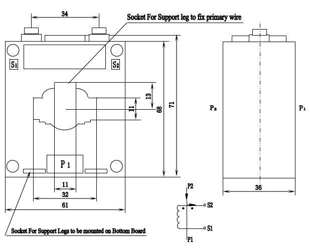
6.Outline Drawing, Installation Dimension and Coil Diagram:(tolerance±1mm)

● Notes:
Two support legs to be mounted on bottom board and one support leg with screws to fix primary wire are included in package along with every product. As to installation instruction, please see the following page.
Installation instruction:
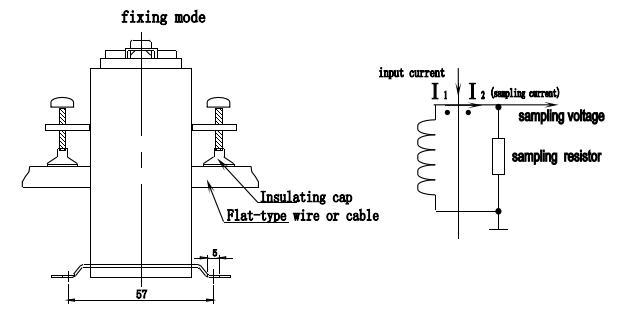
● Mounted on bottom board:
Take two support legs (included in package along with the product) and insert them into the sockets as shown in Fig. below. The center distance between the mounting holes is 57×32.The diameter of the mounting hole for the support leg is Φ 5.0, and then use M5 screw to fix the current transformer on the bottom board.
● Mounted on primary wire:
Take one support leg with M5 hole (included in package along with the product) and insert it into the socket as shown in Fig. below. The center distance between the M5 hole is 57; fix the current transformer on the primary wire with M5 screw.

7.Typical Application and Parameters:
The parameters in this application as shown in the upper right Fig. are listed in table below:
Model | Rated Input Current | Rated Output Current | Rated Sampling Resistance RL | Rated Sampling Voltage | Phase Shift | Non Linearity | Linear Range | Withstand Voltage |
TA4252-1 | 200A | 0.2A | 30Ω | 6V | ≤30’ | ≤0.5% | 3 times of rated value | ≥4KV |
TA4252-2 | 200A | 0.1A | 120Ω | 12V | ≤30’ |
● Notes:
a. In practical applications, it is recommended to use a sampling resistor that is smaller than or equal to the rated value given in the table above, as this can help to improve the non-linearity and phase shift of the device.
b. If the required current ratio is not listed in the table above, we can provide custom-made options to meet specific needs.
8.Attention:
① Connect the primary of the current transformer in series with the measured current loop, and operate the secondary in near short circuit mode.
② Do not allow the secondary of the current transformer to be open circuit and do not install any fuse.