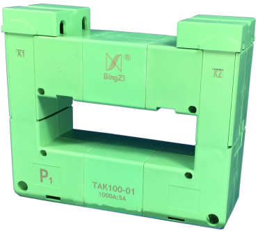
 Beijing TransFar Electronics Group Co., Ltd

1. Features:
① Busbar core-through, flexible wire lead-out, panel installation;
② Fully enclosed, good mechanical and environmental resistance, strong voltage isolation capability.
2. Ambient Conditions:
① Ambient temperature: -55 ℃ ~+85 ℃ ;
② Relative humidity: ≤ 90% at 40 ℃ ;
③ Atmospheric pressure: 860~1060mbar(about 650~800mmHg).
3. Operating Frequency Range : 50Hz~400Hz
4. Insulation Thermal Class: Class B (130℃)
5. Safety Features:
① Insulation resistance:>1000MΩ in normal condition ;
② Insulation withstand voltages: 6000V 50Hz / 1 min ;
③ Fire Retardant: In conformity with UL94-V0.
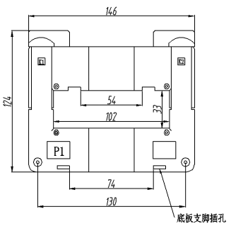
6. Outline Drawing, Installation Dimension and Coil Drawing:( tolerance ± 1mm )
① Outline drawing and installation dimensions are shown in Figure 1 :
②The coil diagram is shown in Figure 2:

Fig 1
● Description: Each product is supplied with two bottom plate feet, two sets of busbar feet and fixing busbar screws. See below for installation instructions.

③
Installation instructions :
● When fixing to the bottom plate :
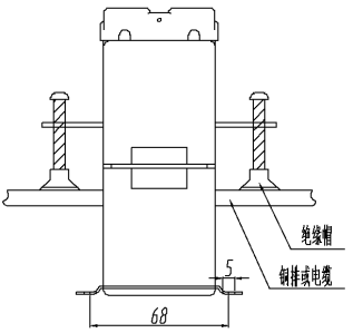
Take the two feet (supplied with the product ) and insert them into the foot sockets on the bottom plate as shown in Figure 3 . The center distance of the mounting holes is 68×84.7; the mounting hole diameter of the feet is Φ5.0; the transformer can be fixed on the bottom plate with M5 screws.
● When fixing on the busbar :
Insert the two feet with M5 holes (supplied with the product ) into the slot of the busbar feet as shown in Figure 3. The center distance of the M5 holes is 59 , and the transformer can be fixed on the busbar with M5 screws.
7. Typical Application and Performance Parameters:
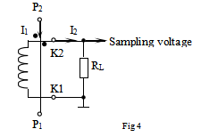
When the sampling voltage is obtained directly by the resistance method ( as shown in Figure 4 ), the performance parameters are shown in Table 1.

Table 1 :
Model | Rated Input Current | Rated Output Current | Rated Sampling Resistance | Rated Sampling Voltage | Phase Shift | Non-linearity | Linear Range |
TAK100-01 | 10 00A | 5A | 0. 3Ω | 1.5V | ≤50' | ≤ 0.5 % | ≥3 times of the rated value |
8.Attention:
① Connect the primary winding of the current transformer in series with the loop of the measured current. Operate the secondary winding in a near short-circuit mode.
② Do not allow the secondary circuit of the current transformer to be open-circuited. Do not connect any fuse in the secondary loop.