 Beijing TransFar Electronics Group Co., Ltd
1.Features:
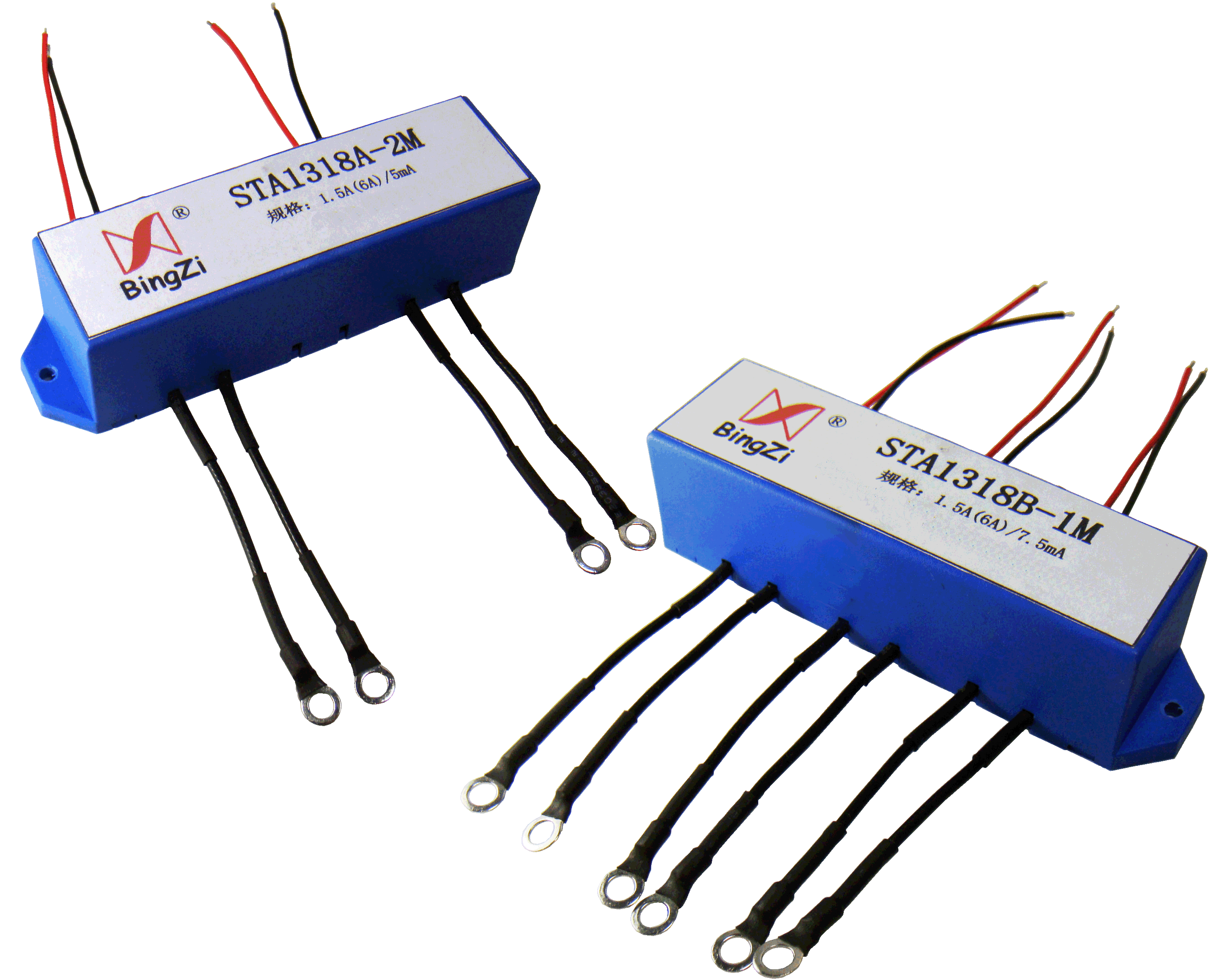
① Fully enclosed, good environmental resistance, strong insulation and isolation capabilities, moisture-proof and shock-proof, and beautiful appearance;
② Different colors of the secondary lead wires of the current transformer facilitate the distinction of terminals with the same name;
③ The use of combined transformers saves more space in the table than the same number of single transformers;
④ The three-phase three-wire circuit adopts two-in-one, and the three-phase four-wire circuit adopts three-in-one .
2.Ambient Conditions:
① Ambient temperature: -55℃~+85℃;
② Relative humidity: ≤90% at 40℃;
③ Atmospheric pressure: 860~1060mbar(about 650~800mmHg).
3.Operating Frequency Range: 20Hz~1kHz
4.Insulation Thermal Class: Class B (130°C)
5.Safety Features:
① Insulation resistance: >1000MΩ in normal condition;
② Insulation withstand voltages: 2.5KV 50Hz/1min.
③ Fire retardancy: In conformity with UL94-V0.
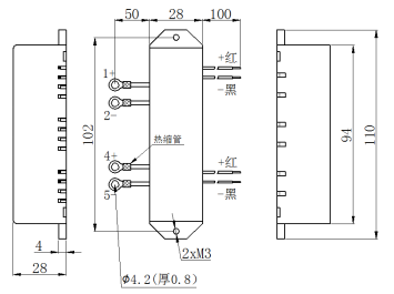
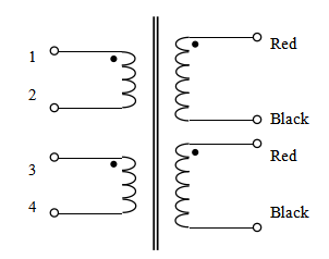
6.Outline Drawing, Installation Dimension and Coil Diagram: (tolerance±1mm)
①Applicable to three-phase three-wire (STA 1318A) outline drawing, installation dimension and coil diagram:
② Applicable to three-phase four-wire (STA1318B) outline drawing, installation size and coil diagram:
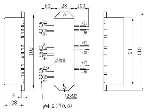
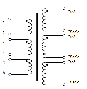
● Note: The lengths of both the input and output leads can be customized according to customer requirements.
7. Performance Parameters:
Model | Rated Input Current | Rated Output Current | Maximum Input Current | Rated Sampling Resistance | Rated Sampling Voltage | Phase Shift | Non-linearity | Linear Range |
STA 1318A-1M (applicable to three-phase three-wire) | 0.5A | 5mA | 2A | 5Ω | 25mV | ≤ 5 ' | ≤ 0.1 % | ≥ 3 times of the rated value |
10Ω | 50mV | ≤ 5 ' | ≤ 0.1 % | |||||
20Ω | 100mV | ≤ 10 ' | ≤ 0.2 % | |||||
40Ω | 200mV | ≤ 10 ' | ≤ 0.5 % | |||||
STA 1318A-2M (applicable to three-phase three-wire) | 1.5A | 5mA | 6A | 5Ω | 25mV | ≤ 5 ' | ≤ 0.1 % | ≥ 3 times of the rated value |
10Ω | 50mV | ≤ 5 ' | ≤ 0.1 % | |||||
20Ω | 100mV | ≤ 10 ' | ≤ 0.2 % | |||||
40Ω | 200mV | ≤ 10 ' | ≤ 0.5 % | |||||
STA1318B-1M (applicable to three-phase four-wire) | 1.5A | 7.5 mA | 6A | 5Ω | 37.5mV | ≤ 5 ' | ≤ 0.1 % | ≥ 3 times of the rated value |
10Ω | 70mV | ≤ 5 ' | ≤ 0.1 % | |||||
20Ω | 150mV | ≤ 10 ' | ≤ 0.2 % | |||||
40Ω | 300mV | ≤ 10 ' | ≤ 0.5 % | |||||
STA1318B-2M (applicable to three-phase four-wire) | 5A | 5mA | 20A | 5Ω | 25mV | ≤ 5 ' | ≤ 0.1 % | ≥ 3 times of the rated value |
10Ω | 50mV | ≤ 5 ' | ≤ 0.1 % | |||||
20Ω | 100mV | ≤ 10 ' | ≤ 0.2 % | |||||
40Ω | 200mV | ≤ 10 ' | ≤ 0.5 % |
● Notes:
a. In practical applications, the sampling resistance should be less than or equal to the rated value given in the above table, which will improve the nonlinearity and phase shift;
b. If the conversion ratio required by the user is different from the above, it can be customized according to the user's requirements.
8. Attention:
① Connect the primary winding of the current transformer in series in the circuit under test. Operate the secondary winding approximately in a short-circuit state.
② Do not allow the secondary circuit of the current transformer to be open-circuited. Do not install any fuses in the secondary circuit.